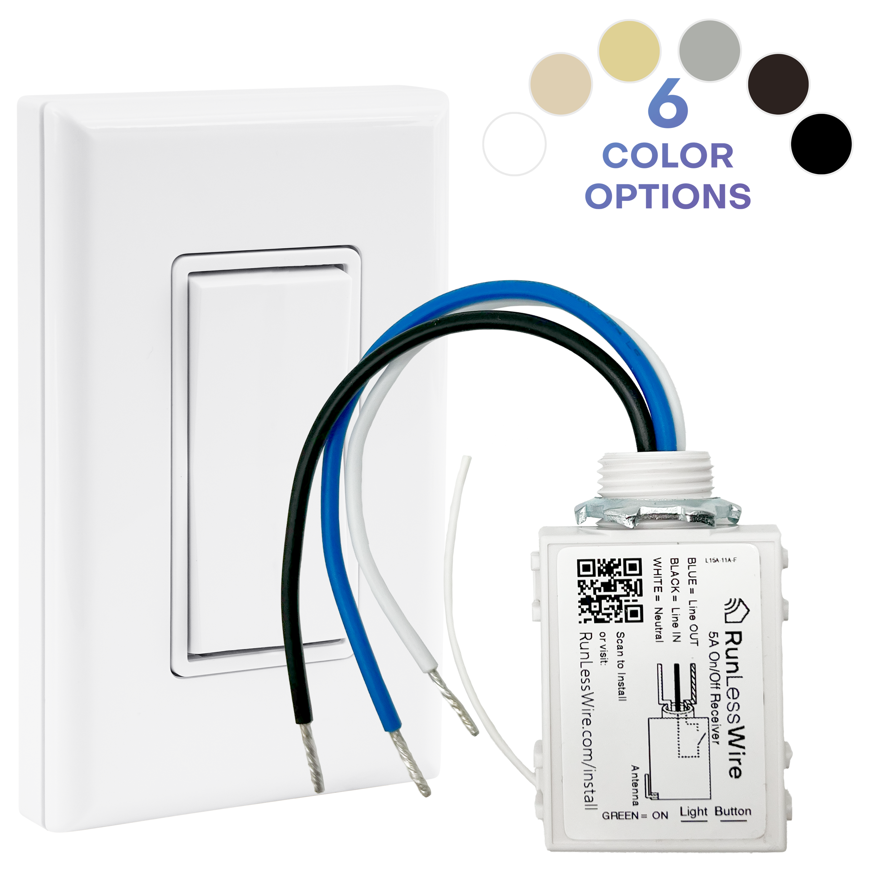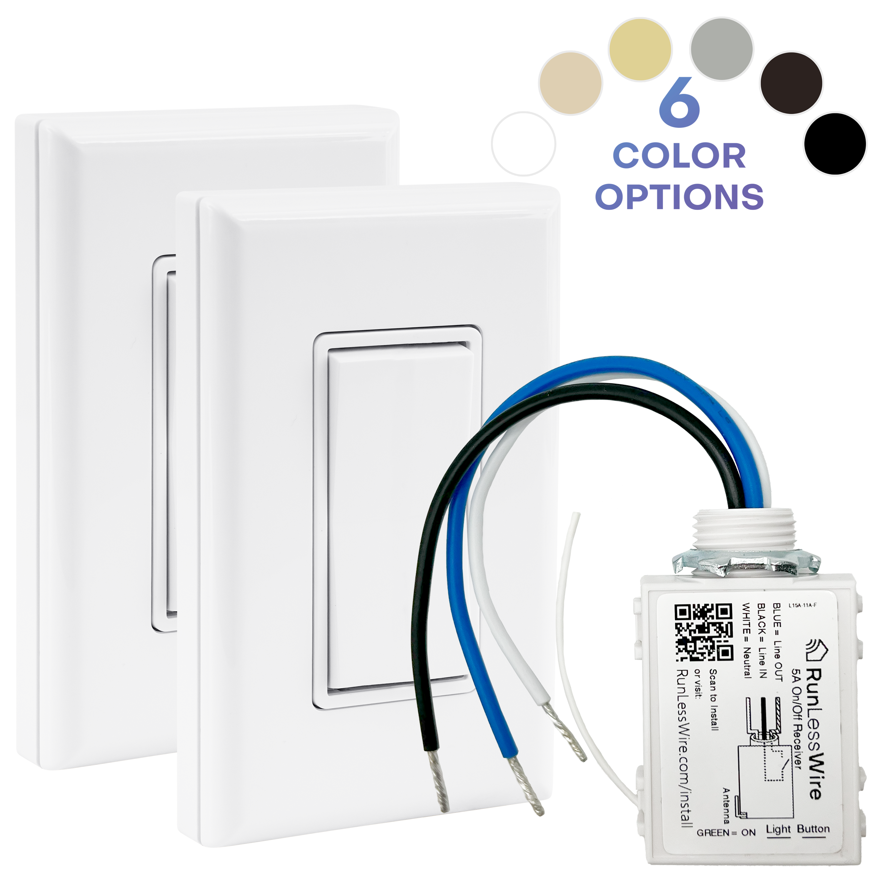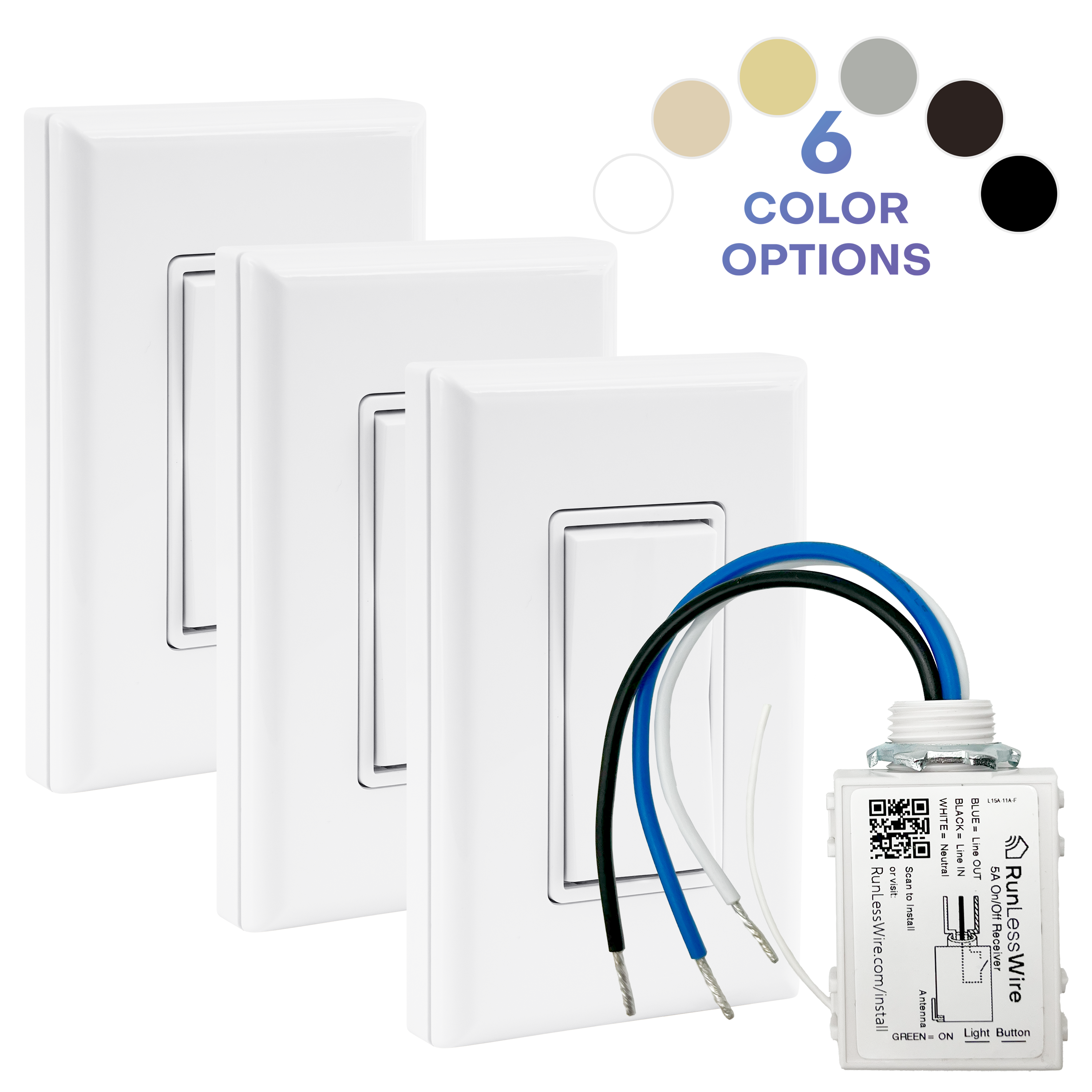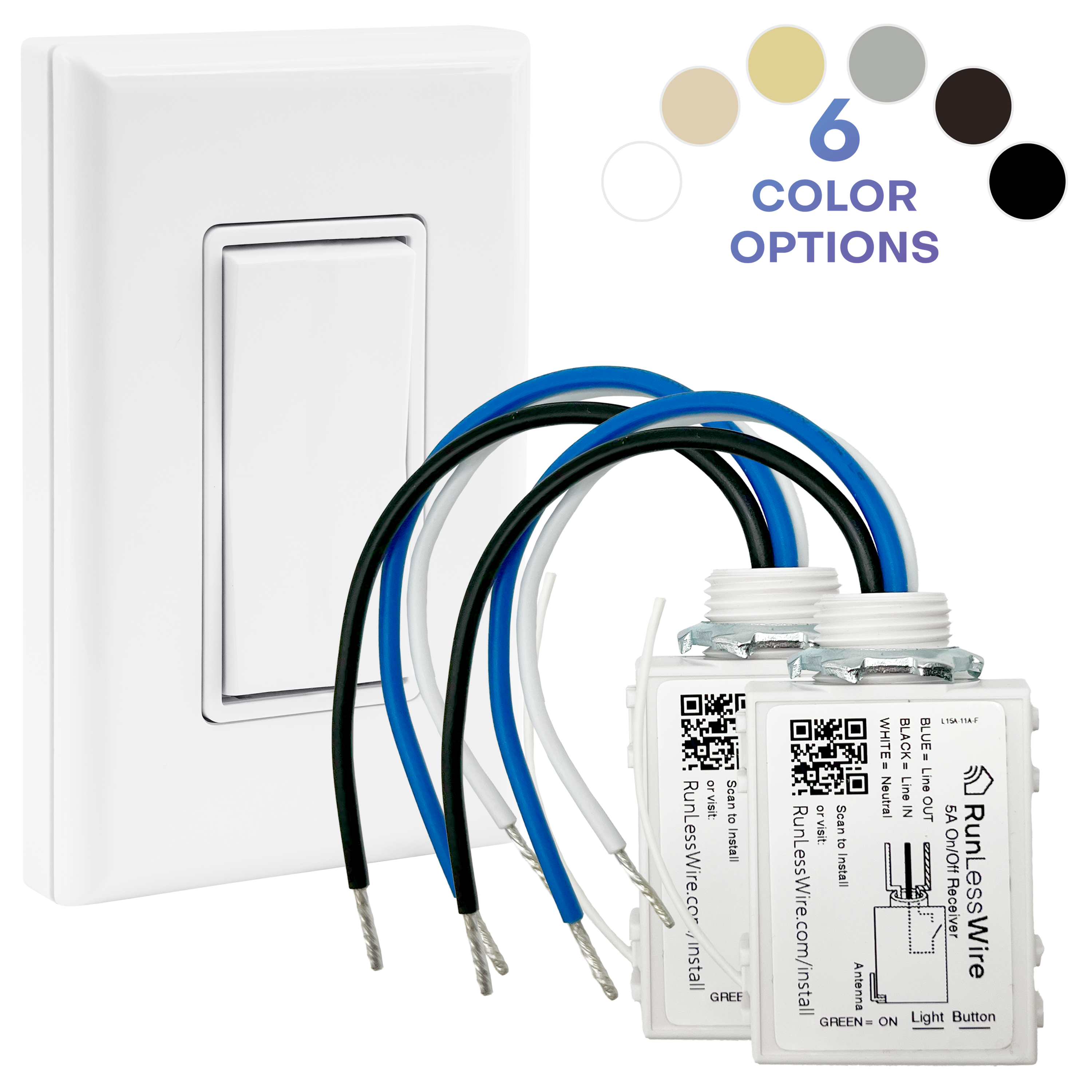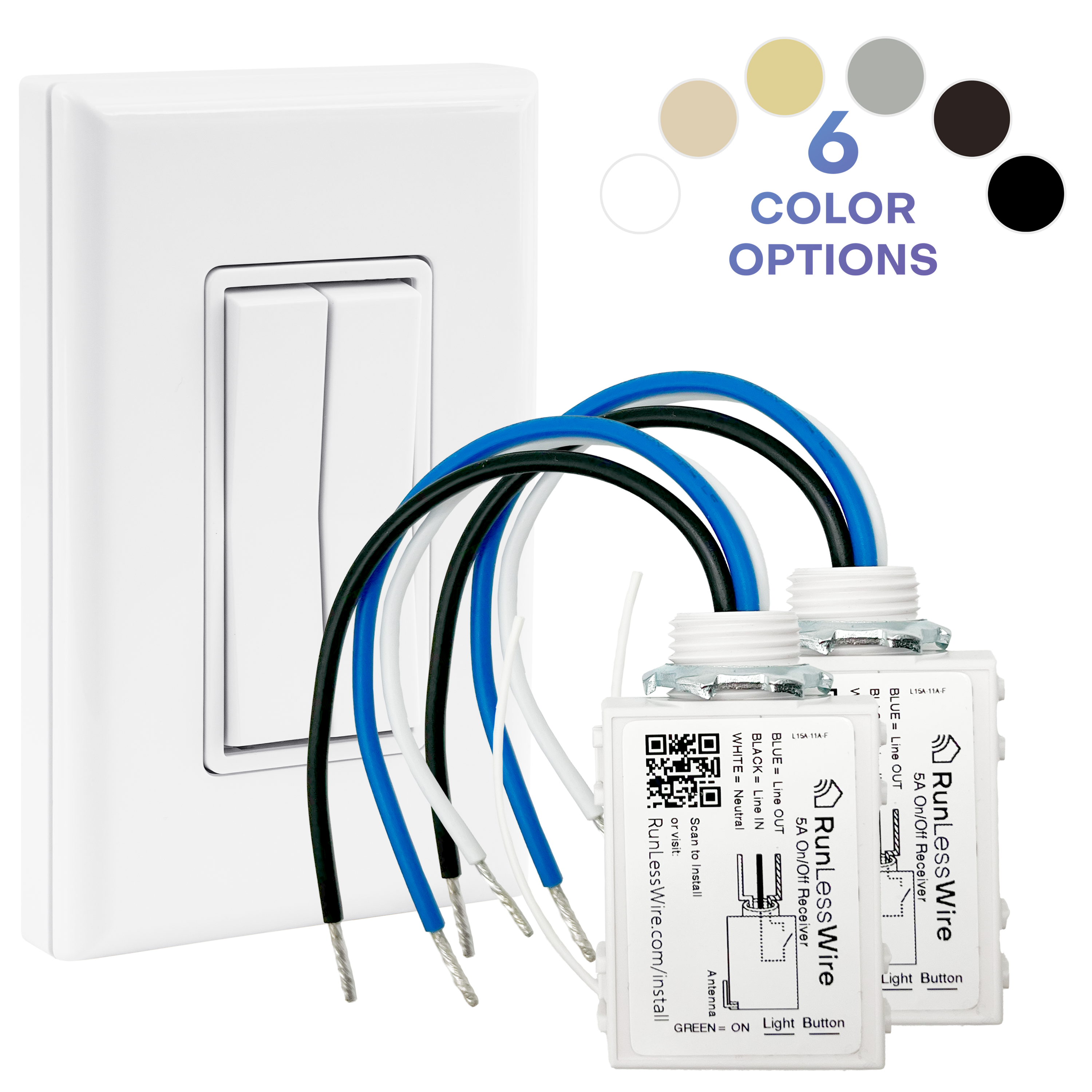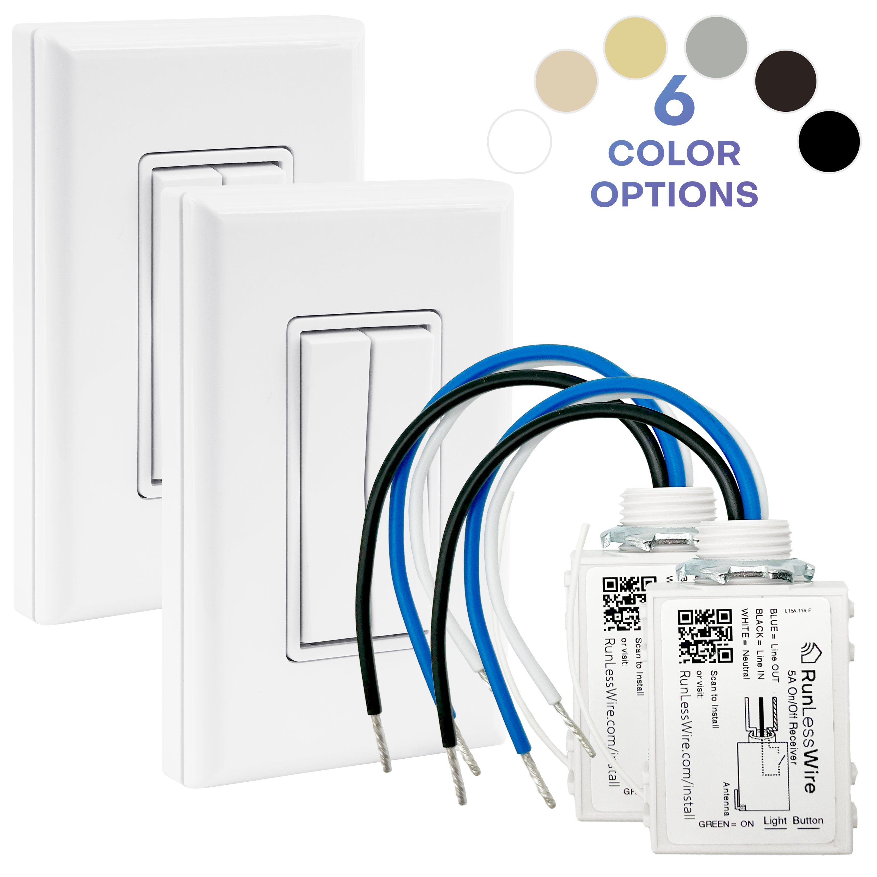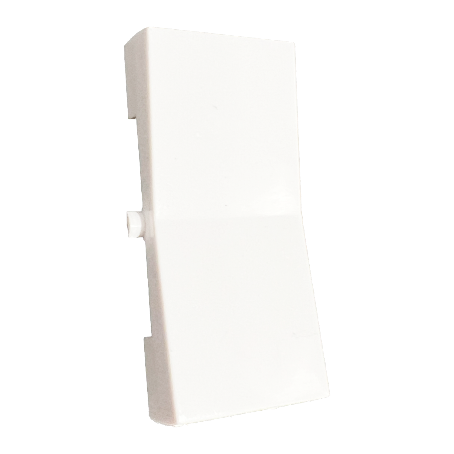
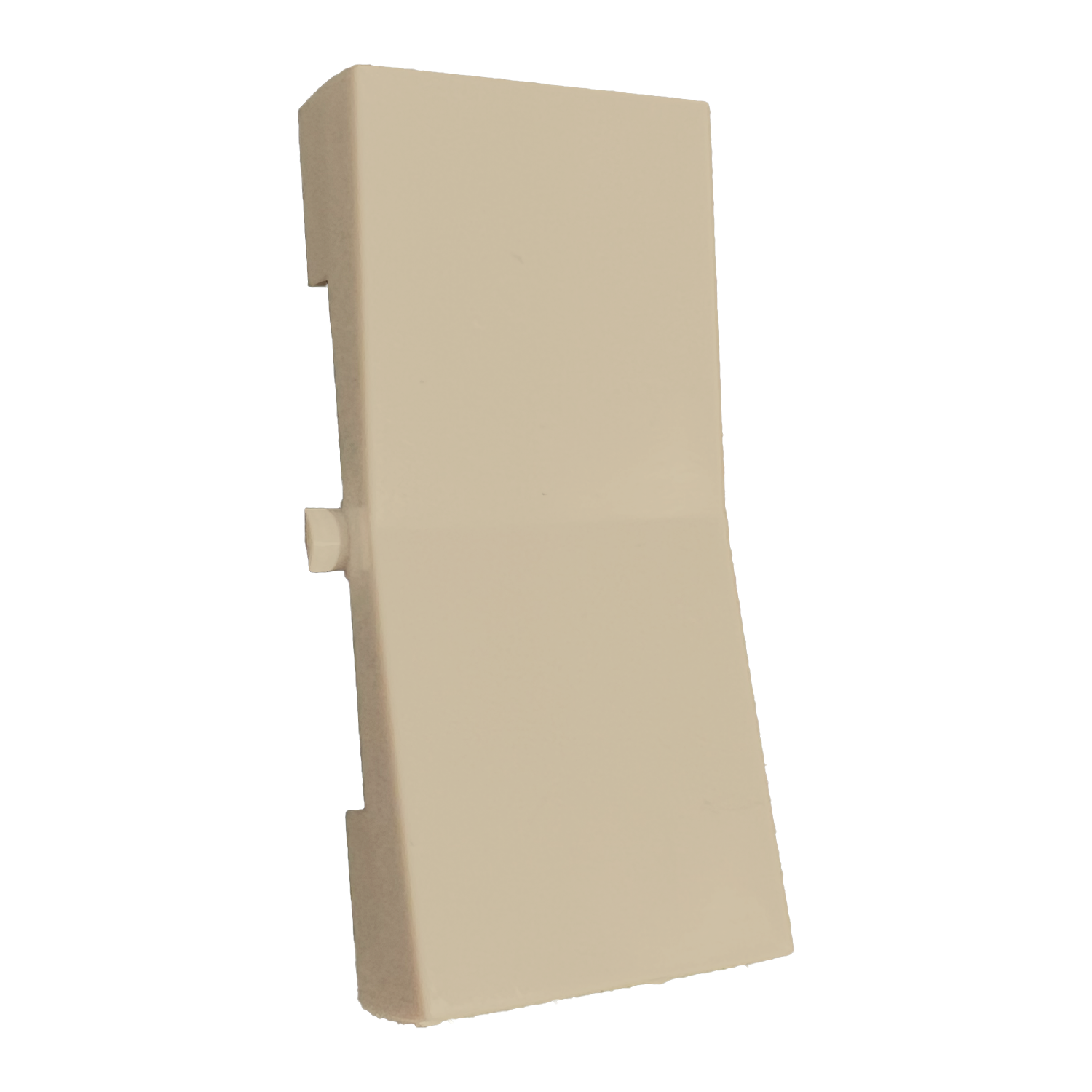
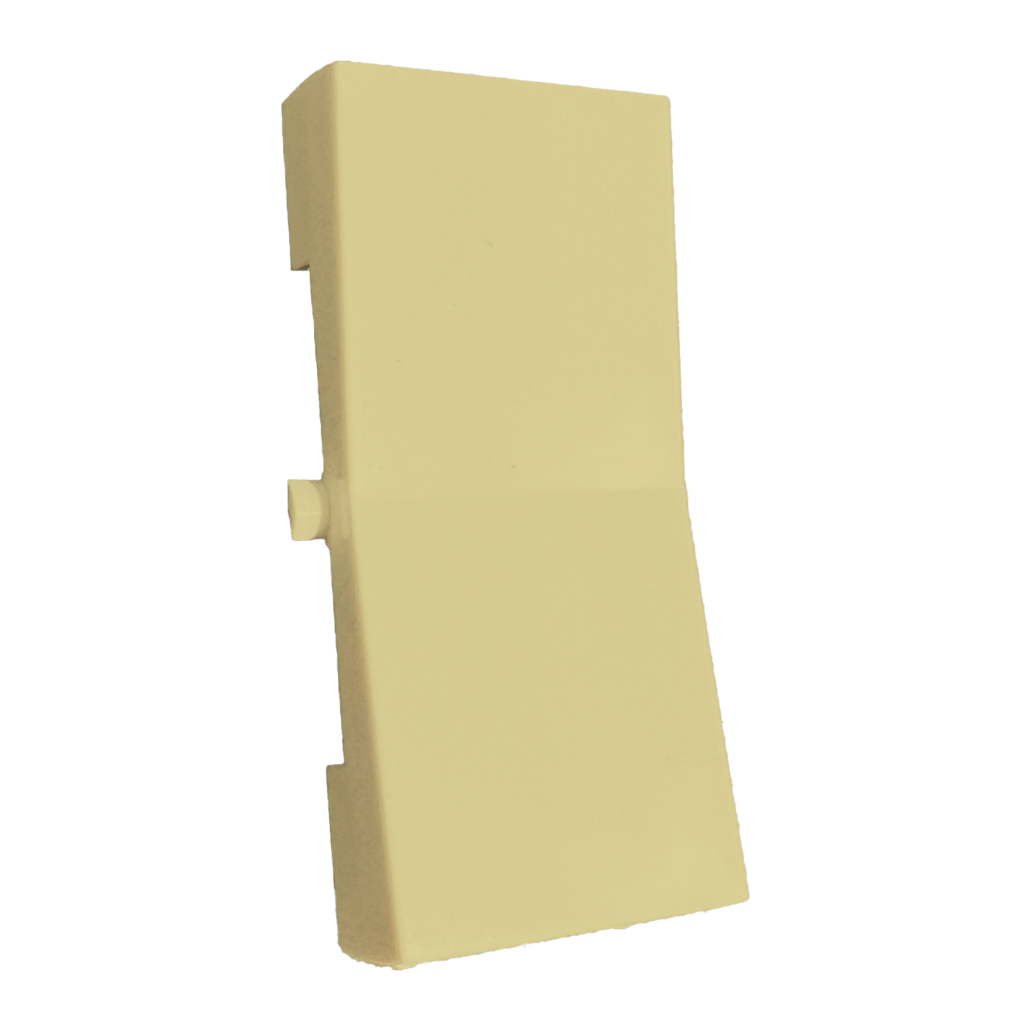
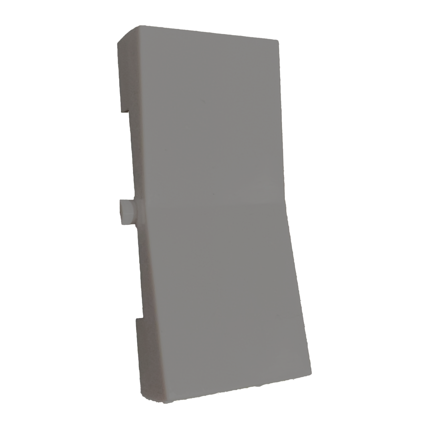
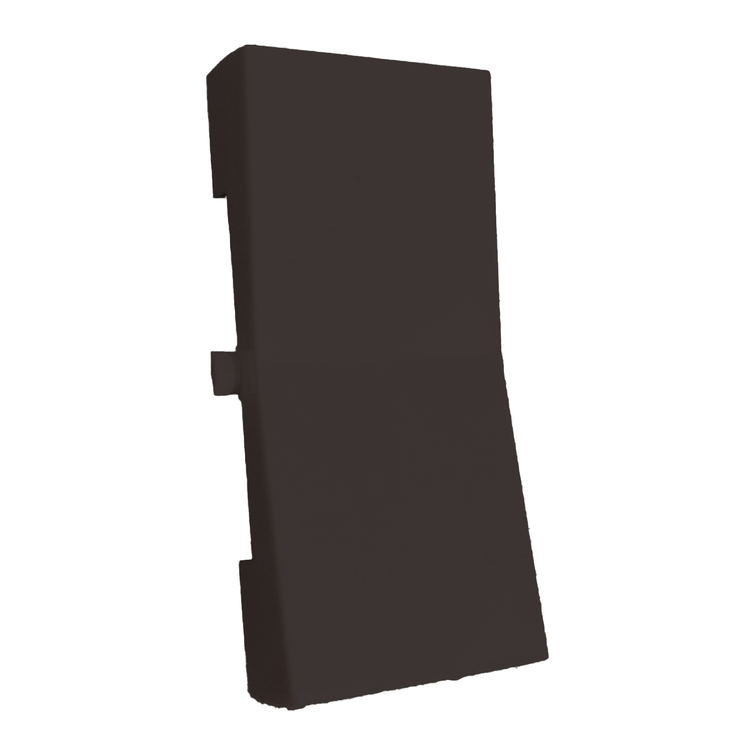
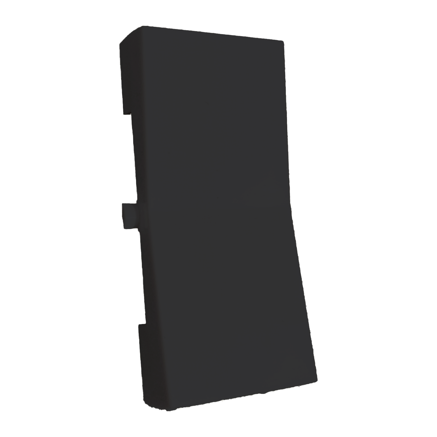
SINGLE ROCKER BUTTON PLASTIC
This is just the plastic rocker button part of the switch.

Additional Information
SELF-POWERED by kinetic energy, eliminating the need for wires, batteries, or WiFi - never worry about changing out the batteries, EVER!
5-YEAR WARRANTY: Assembled by hand in the USA and made with premium quality materials.
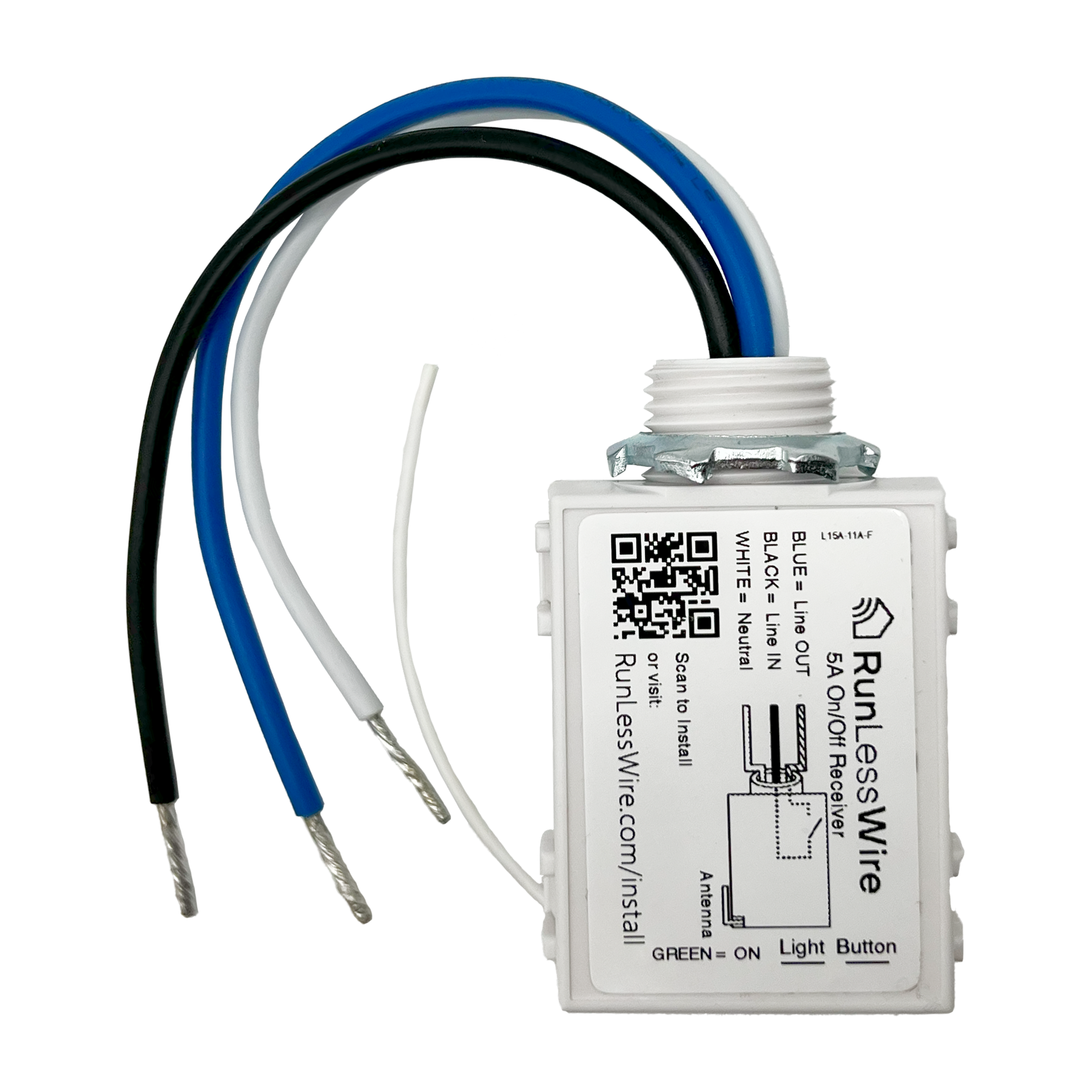
EASY INSTALLATION: Be your own electrician with this simple DIY hack. Install the receiver at the fixture or the original switch location, neutral wire required. Each kit comes pre-paired and includes all hardware needed.
MOUNT ANYWHERE: Place the switch on any flat surface, replace a wall switch, or use as a remote control.
ECO-FRIENDLY: Save money on materials and electrical costs.
AS SEEN ON Ask this Old House.
If you are not 100% satisfied with your purchase, you can return the product and get a full refund or exchange the product for another one, be it similar or not. You can return a product for up to 30 days from the date you purchased it. Any product you return must be in the same condition you received it and in the original packaging.
This product is warranted against defects in materials and manufacturing under normal use in accordance with instructions and specifications published by RunLessWire, for a period of five (5) years from the date of purchase by the End User. In the event of a product failure due to materials or workmanship, RunLessWire will repair or replace the defective product. For warranty service, email support@runlesswire.com with your order information and the issues you are experiencing, for a Return Authorization and to return the defective product (shipping prepaid) for prompt repair or replacement.
RunLessWire ships Monday through Friday excluding holidays. The shipping cut-off time is 10am MST. Orders placed after 10am MST will be processed the next business day. Shipping is via USPS First class or Priority mail depending on the quantity. Typical delivery times are 3-5 business days from date of order. Shipping price and delivery time will vary on international orders.
Range: 50-150 feet (typical)
Frequency: 902 MHz EnOcean® Protocol
Power Supply: Self-generated when switch is pressed
Buttons: 2 Buttons (1 rocker) or 4 Buttons (2 rockers)
Output Channels: Only limited by number of receivers in range
Dimensions: 2.75(W) x 4.5(H) x 0.62(D) inches
Operating Temperature: -13° to +149°F (- 25° to + 65°C)
Radio Certifications: FCC (United States): SZV-PTM200C 210C or 210U I.C. (Canada): 5713A-PTM200C 210C or 210U
Addressing: Factory set unique ID (1 of 4 billion)
Range: 50-150 ft. (typical)
Frequency: 902 MHz
Power Supply Input Rating: 100-240 VAC 50/60 Hz
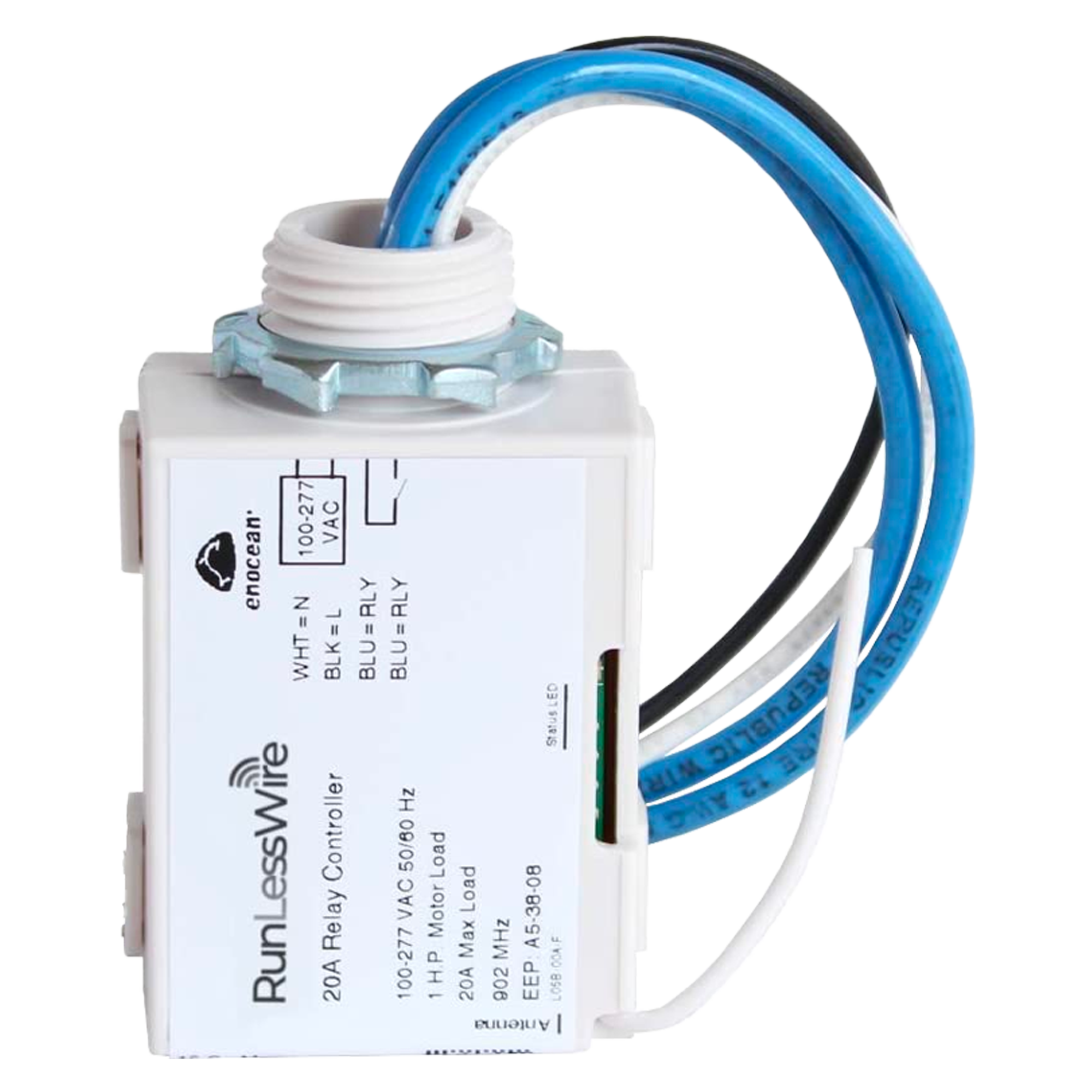
Relay Output: 1 Form A Relay 5A
Max Loads / Contact Ratings: Resistive Load 5A, Tungsten 600W, Florescent 600W, LED Lamp 200W
Memory: Link up to 10 switches
Operating Temp: -40° - 104° F (-40°-60° C)
Dimensions: 1.1"(L) x 1.6"(W) x 3.3"(H)
Radio Certification: FCC (United States)
TECHNICAL DETAILS
Indoors Only: Switches and receiver are not weatherproof and should be used indoors; a receiver or switch installed on an outdoor light will need protection from the elements.
Pre-linked: Switches and receiver are shipped to you already linked together for a quicker installation.
Range: The range of switch is 50-150 feet from the receiver, depending on walls and barriers. Test desired distances before completing installation.
Interference: Multiple units may be used in the same home without interference. Unique radio frequency won’t interfere with other devices.
Power Supply: Receiver requires AC input. Switches are self-powered and require no power supply.
Easy Install: Our small receiver is simply wired between the power and the fixture, and then stored in the light box behind, or at the fixture location. Mount the switch anywhere with industrial tape or screws. Also used to replace outdated, undesired current switches.
COMPARE WIRELESS SWITCH KITS
Control 1 circuit with 1 switch
Control 1 circuit with 2 switches
Control 1 circuit with 3 switches
Add to pull-chain, relocate switch
Stairway, hallway, large room
Add a remote to 2 wall switches
1
2
3
1
1
1
Single Rocker
Single Rocker
Single Rocker
5 Amp - handles up to 600W
5 Amp - handles up to 600W
5 Amp - handles up to 600W
Control 2 circuits with 1 switch
Control 2 circuits with 1 dual switch
Control 2 circuits with 2 dual switches
Garage lights, sconces, bathroom lights with 2 fixtures
Fan & Light, 2 lights separately from same switch
Fan & Light + and extra switch
1
1
2
2
2
2
Single Rocker
Dual Rocker
Dual Rocker
5 Amp - handles up to 600W
5 Amp - handles up to 600W
5 Amp - handles up to 600W
ALL WIRELESS LIGHT SWITCH KITS
QUESTIONS & ANSWERS
Yes, each unit is assigned a unique digital ID and communicates only with other units specifically associated through a linking process.
25 switches can be linked to one controller.
The only limit is the wireless range. Multiple controllers may be linked to each switch.
A 3-way switch kit includes 2 wireless switches to which replace any existing wired switches. The controller replaces existing switches and does not work with them.
Typically between 50 and 150 ft. Range. The equipment nearly always works reliably within a 50’ radius and can work at longer distances.
Range is affected by:
Proximity to metal – keep away from metal to increase distance, use plastic boxes instead of metal where possible
Obstructions – Wireless signal transmits through most materials at least some distance. Materials in order of range reduction, minimum to maximum: glass, sheetrock, wood, aluminum siding, sheet metal, stucco (w/ wire mesh), brick, concrete
Interference – Some 900MHz wireless microphone systems are known to reduce the reliability of the wireless switches. There are no other known sources of interference.
The products use no batteries and include an integrated magnetic generator. They are designed with a 20+ year intended lifespan. They have a 5 year warranty.
Confirm the controller has power and the Status LED is Green (Output ON) or Red (Output OFF). Hold the MENU button until a click is heard – about 5 seconds. Buttons may be hidden under a sticker.
Click the top button of the switch 3 times. The status LED will pause GREEN for 3 seconds indicating that the switch ID has been added to the controller’s memory. If status LED pauses RED, the switch has been removed from memory; click the switch 3 more times to add it back.
Wait 30 seconds until clicking / blinking stops. Operate switch.
RunLessWire switches and controllers communicate using the 902MHz frequency. It will not interfere with Wifi (2.4GHz or 5.8GHz) or most other wireless devices.
Each unit is assigned a unique digital ID (one of 4 billion) and there cannot be cross talk, even though they transmit on the same frequency.
Watts = Amps x Voltage. So, for example, with the 5 amp RLW controller: 5A x 120V = 600 Available Watts
Email: support@RunLessWire.com
Phone: 866.600.2111
9am-5pm MST, M-F
The controller does not respond to the wireless switch:
1. Confirm the controller is wired correctly and functional:
-The status light on the controller should be illuminated. Green means the output should be ON, Red means the output should be OFF. No status light indicates that power is not on, wiring is incorrect, or Controller has been damaged.
-Press the “Select” or “Test” button to toggle the controller output. Subsequent presses will cycle between ON and OFF. If the status light changes color and the light doesn’t respond there may be a wiring problem. If the relay doesn’t click, the relay may be damaged from an overload condition.
2. Confirm the switch is functional:
-Click the switch and confirm that the controller status light flickers. Each time the switch transmits, whether it is linked or not, the status light should flicker briefly. If it does not flicker, either the switch isn’t transmitting or the controller isn’t receiving.
-Link the switch to the controller. Hold the “Menu” button for about 5 seconds until the controller clicks, then release. While the controller is clicking, press one button on the switch 3 times. The controller status light will pause GREEN when the switch is added to the controller memory. The status light will pause RED when the switch is removed from the memory. If this happened, click the switch 3 more times to add it to the memory. If clicking the switch doesn’t not link, the switch may be damaged. If a second switch is available and works, then the first switch can be confirmed defective. If not, contact RunLessWire for support and warranty service if applicable.


